

400kW Diesel Generator Manufacturing Process and Key Quality Considerations
2026-10-19
When a 400kW diesel generator has to keep a hospital, factory, or data center running during a blackout, the difference between seamless backup and costly downtime often comes down to how it was built. At DINGBO POWER, we believe manufacturing precision and rigorous quality checks are not add-ons but the foundation of every unit that leaves our floor. This post walks you through the key stages of our 400kW generator production and the quality considerations that ensure reliable performance when it matters most.
Frame welding and alignment tolerances that keep a 400kW set from shaking itself apart
At 400kW, the frame is not just a support structure; it is the primary defence against self-destruction from torsional vibration. Every weld at the cross-member junctions is specified as a full-penetration butt weld with no undercut permitted, and the rail ends are ground flush before the engine and alternator feet are seated. This removes the small stress risers that turn harmless static loads into fatigue cracks once the set runs through its critical speed range. The chassis is laid on a flat granite table after welding and checked with a dial indicator run along the mounting rails. Any local dip or rise greater than 0.12mm over a 250mm span is corrected by controlled heat straightening, not by shimming under the engine feet.
Alignment between the crankshaft centreline and the alternator rotor shaft is set with the coupling bolts removed, so the two flanges are drawn together only by hand feel. We use a pair of laser emitters mounted on each shaft and read the angular and offset error in two planes at 90-degree intervals. The acceptance window is tight: parallel offset no more than 0.05mm and angular misalignment under 0.07mm per 100mm of flange diameter. After the final weld inspection and a 24-hour rest period, the alignment is re-checked with the set at operating temperature, because thermal expansion in a 400kW block can shift the shaft centreline by more than the allowed offset if the frame was not stress-relieved.
A 400kW set produces a firing frequency that can excite frame bending modes in the 40–90Hz band, so the final test is not just a no-load run. The unit is loaded in 25% steps to full rated output and held at each point long enough for the rubber mounts to settle. Vibration velocity is logged at the four generator feet and the engine bell-housing. If any reading drifts above 4.5mm/s RMS or shows a sudden jump between 60% and 80% load, the engine is stopped and the alignment is re-verified before the paint has even cured. That is the difference between a set that runs 20,000 hours and one that breaks its own mounting bolts in the first season.
Why engine-to-alternator coupling checks catch failures before the test bay
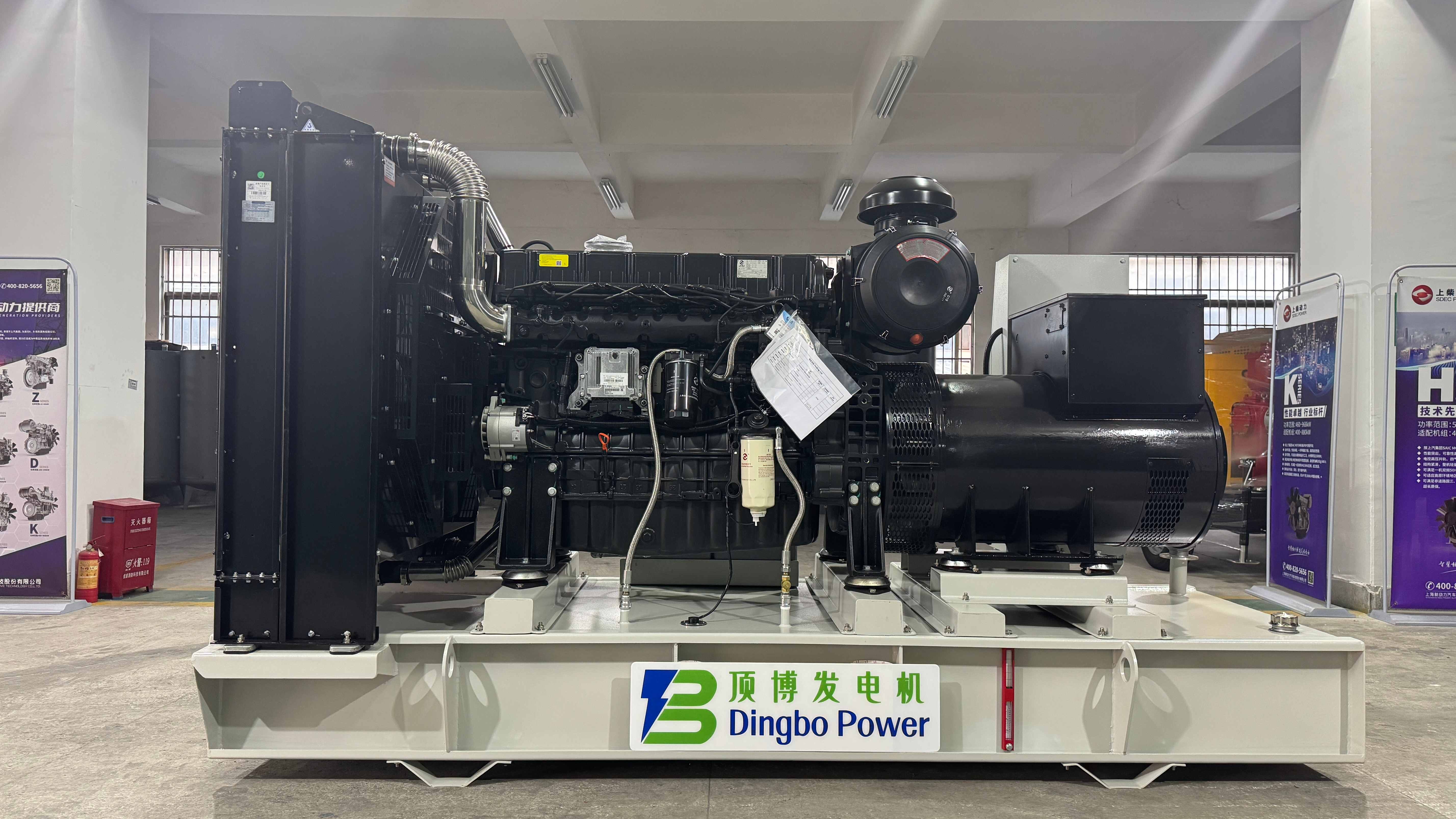
A coupling that measures within spec on the bench can still be a few thousandths out once the engine mounts flex under load. Checking the alignment cold, then again after the first torque pulse, exposes a soft foot or a bell housing that shifts. On the test bay, that small movement turns into a cracked adapter plate or a wiped input bearing, and the data log shows a vibration spike that gets blamed on the controller instead of the joint.
Bolt torque patterns matter more than the final number. A star pattern with two passes seats the flange evenly. If one bolt is tighter than its neighbor, the coupling face cocks under load and the rubber element starts chewing itself. Laying a straightedge across the flange and slipping a feeler gauge under the low side catches that before the alternator ever spins up. The same check after a few heat cycles reveals fasteners that relax because the paint under the washer compressed.
Hand-rotating the assembly with the injectors disabled gives a feel for roughness that instruments miss. A notchy spot every 180 degrees points to a bent shaft or a brinelled bearing. If the coupling passes the hand check but the alternator rotor has visible runout at the drive end, the test bay will find it at full speed. Fixing it in the shop costs an hour; finding it on the dyno costs a day and a set of sensors.
Cooling circuit assembly points where small leaks become warranty claims
On the production line, the cooling circuit seems straightforward until you look at the junction between the plastic end tank and the aluminum core. It’s there, under thermal cycling, that the crimp relaxes by a few microns. Not enough to see with the naked eye, but enough for a coolant trace to wick through and leave a white residue after a few thousand miles. By the time the customer notices a sweet smell in the cabin, the leak has already etched a path along the gasket face. Warranty teams see the same photos again and again: a faint green stain at the lower corner of the radiator, exactly where the assembly fixture applies uneven pressure during the crimping stroke.
Hose connections add another layer of trouble. The quick-connect fittings on heater cores and oil cooler lines are designed for fast installation, but the O-ring groove depth varies by less than a tenth of a millimeter between suppliers. When the groove is slightly shallow, the O-ring compresses too much on one side, sets in place after heat aging, and then lets coolant seep past during cold-start pressure spikes. It’s not a gusher—just a slow film that gathers dust and forms a crusty ring at the fitting. Technicians often misdiagnose it as a loose clamp, tighten it further, and crack the plastic housing. Then the real leak starts, and the repair bill triples.
The water pump seal is another classic. Under high-speed operation, a tiny amount of coolant bypasses the mechanical seal by design to lubricate the faces. But if the seal’s silicon carbide face has a micro-void from the sintering process, that weep turns into a drip. It collects at the pump’s weep hole, evaporates during short trips, and leaves a telltale pink or orange stain on the block. Owners ignore it until the bearing fails or the coolant level drops enough to trigger a warning light. At that point, the warranty claim includes not just the pump but the tensioner, belt, and sometimes the thermostat housing—all because a five-cent manufacturing anomaly escalated into a system failure.
Paint prep and corrosion resistance beyond the standard salt spray checkbox
If you’ve ever watched a freshly painted panel rust from the inside out after just one winter, you already know that passing a 500-hour salt spray test doesn’t mean much in the real world. Real corrosion starts where the spec sheet ignores: inside blind cavities, under loosely clinched flanges, and along edges that were never properly dressed. The difference between a coating that survives a lab cabinet and one that survives a gravel road comes down to how seriously you take the unglamorous work before the spray gun ever fires.
That means ditching the idea that a quick wipe with solvent counts as surface prep. On bare steel, we’re looking for an anchor profile deep enough to give the primer something to bite into, not just a cosmetic scuff. On aluminum, that means removing the oxide layer, not smearing it around. And on mixed-metal assemblies, it means isolating fasteners and seam sealers so you don’t create a galvanic cell that eats itself from day one. These steps don’t show up on a glossy brochure, but they’re what separate a ten-year finish from a two-year warranty claim.
The same applies to paint selection. Too many shops pick a primer because it sprays easy and blocks fast, then wonder why stone chips turn into rust blooms within months. Look instead for systems that stay flexible after full cure, that resist cathodic disbondment at scribe lines, and that don’t rely on a single thick topcoat to hide poor film build in corners. Run a filiform corrosion test, not just neutral salt spray. Cycle the panels through humidity and UV. Then compare the results with what you actually see on vehicles coming back from the field. That’s the checkbox that matters.
Load bank testing sequence for a 400kW diesel generator that reveals real-world weak spots
A standard load bank test on a 400kW diesel generator often skips over the moments that actually matter. Instead of stepping up in neat 25% increments, try a sequence that mirrors genuine site conditions: hold at 30% for fifteen minutes to expose lazy voltage regulators, then jump straight to 70% and watch how the governor reacts when the block heater is still warm. That sudden shift catches fuel delivery hesitations and turbo lag that a slow ramp never shows.
The real weak spots surface during the cool-down phase, not the peak. After running at full load for twenty minutes, cut the load bank to 10% and let the engine settle for five. A healthy unit will hold frequency within half a percent. If the speed droops or hunts, you have a sticky fuel rack or a governor that needs re-calibration. Then apply a single large block load—around 60%—to a cold generator after a ten-minute idle. That cold-start block test reveals battery capacity, starter motor condition, and whether the alternator can recover voltage quickly enough for motor starting applications.
Finally, run an unbalanced load test across all three phases at 40% total, with one phase carrying double the others. Most 400kW sets are rated for balanced loads only, and an unbalanced test will quickly highlight uneven winding temperatures or a voltage regulator that cannot maintain phase-to-phase stability. Let the unit run for thirty minutes in this condition—if the exhaust note changes or the control panel throws a phase imbalance alarm, you have found the weak spot that a traditional three-step test would never touch.
Torque marking and fastener control steps often skipped on the final line
On many final assembly lines, torque marking and fastener control steps get quietly dropped when the pace picks up. Operators under time pressure often see the extra pass with a paint pen as optional, especially if the tooling already shows a green light. The assumption is that if the wrench clicked, the joint is tight enough—so why bother marking it? This attitude spreads fast when supervisors don’t reinforce the step, and soon the marking station becomes a decorative afterthought rather than a checkpoint.
Skipping these controls doesn’t just create paperwork gaps; it opens the door to real failures. A bolt that was torqued but never marked can be mistaken for one that was never checked, leading to double work or, worse, a missed loose joint. On vehicles or heavy equipment, a single unmarked fastener in a critical location—like a suspension link or steering component—can trigger a recall that costs far more than the few seconds saved on the line. Fastener control is the last line of defense against assembly drift, and without visible proof, audit teams have no way to trace whether the right sequence was followed.
To keep these steps from being bypassed, some plants have moved away from relying on operator memory. Simple changes help: integrating the torque validation directly into the tool so the marking pen only releases after a confirmed cycle, or using pre-inked markers that require no extra motion. Others have added a short camera check at the end of the line that flags any fastener without a witness mark before the unit leaves the station. The key is making the control step feel less like an add-on and more like a natural part of the torque process itself.
FAQ
The initial phase involves frame fabrication and stator core stacking, but what often gets overlooked is the precise alignment of the rotor shaft before any winding begins. If the shaft runout exceeds a few thousandths of an inch, vibration will plague the unit under load, drastically shortening bearing life.
The winding and insulation process. The way the stator windings are inserted, secured, and varnished determines how well the generator handles heat cycling and moisture. Poor varnish impregnation leads to partial discharge and eventual insulation breakdown, especially at 400kW where thermal stress is significant.
They typically use a laser alignment tool or dial indicators on the coupling faces. The tolerance is often within 0.05 mm. After that, a torsional vibration analysis may be run to confirm the natural frequency of the combined rotating assembly does not coincide with the engine operating speed range.
The fuel injection pump and injectors are flow-tested on a bench before installation. During final testing, fuel pressure, return flow, and injector spray pattern are verified. Since 400kW engines often run at high load, any discrepancy in fuel delivery can cause uneven cylinder temperatures and premature wear.
A load bank test applies a resistive or reactive load to the generator at full rated output, verifying that the engine can sustain 400kW without overheating, the voltage regulator holds frequency and voltage within limits, and all safety shutdowns function. It also helps seat the piston rings and burn off any assembly lubricants.
The radiator core must be pressure-tested to at least 1.5 times the operating pressure. Coolant passages are flushed to remove casting sand. The thermostat is calibrated, and the fan is balanced as an assembly. Many manufacturers also do a thermal imaging check on the radiator during full-load testing to spot hot spots or airflow restrictions.
Each control module undergoes a functional test simulating various fault conditions like low oil pressure, high coolant temperature, and overspeed. The automatic transfer switch logic, if included, is also tested for correct starting and stopping sequences. Wiring harnesses are checked for continuity and insulation resistance.
At 400kW, the thermal and mechanical stresses are high enough that parts like the engine block, crankshaft, and alternator frame are often subjected to additional non-destructive testing, such as ultrasonic or magnetic particle inspection. Smaller generators might only get visual and dimensional checks, while larger ones require more rigorous verification of material integrity and weld quality.
Conclusion
Frame welding sets the baseline. On a 400kW set, the chassis sees torsional and vibration loads that quickly expose poor fit-up. Alignment tolerances are held tight—typically within a millimeter across the skid—so the engine and alternator mounts stay parallel under load. Weld sequencing matters too, because heat distortion can pull the rails out of square before the set ever reaches the test bay. Coupling checks between engine and alternator catch misalignment early; a dial indicator runout above spec means the bellhousing or flex plate will fail prematurely. Those checks are done before any fuel is burned, saving the cost of a teardown after load testing.
Cooling circuit assembly is another place where small leaks become warranty claims. Each hose joint, clamp position, and radiator drain gets a pressure test that holds for a set period—not just a visual once-over. Paint prep is more than salt spray; the steel is blasted or phosphated to remove mill scale, then primed and top-coated with attention to edges and weld spatter, because corrosion starts at those spots. On the final line, torque marking and fastener control often get skipped, but every critical bolt—engine mounts, alternator coupling, exhaust flanges—gets a witness mark after the torque wrench. Load bank testing then runs the set through stepped loads, transient response, and sustained full load, revealing weak points like overheating at a specific RPM or a voltage dip that only shows under real reactive loads. That sequence catches what static inspections miss.
Contact Us
Contact Person: Rita
Email: [email protected]
Tel/WhatsApp: +8613481024441
Website: https://www.dbdieselgenerator.com/