

OEM Split-Core Residual Current Transformer Applications and Buying Tips
2026-09-07
Choosing the right split-core residual current transformer for OEM projects can mean the difference between smooth installations and costly retrofits. Whether you're integrating earth leakage protection into EV chargers, smart distribution boards, or industrial motor controls, the transformer’s split-core design eliminates the need to disconnect cables—saving time and reducing downtime. In this post, we break down real-world applications and share practical buying tips you won't find in typical datasheets. As a leading manufacturer, Xiasen has seen firsthand what separates a reliable OEM partner from a source of recurring field failures.
Retrofit Jobs Where a Split-Core Residual Current Transformer Saves the Day
Older industrial control panels often run on tight budgets and even tighter space, leaving little room to pull cables for a traditional solid-core RCD. That’s where the split-core version comes in—you can wrap it around an existing conductor without shutting down the whole line, then bolt the halves back together in seconds. The savings show up immediately in labour hours, but the real win is avoiding a full rewiring project just to add earth-leakage protection.
Retrofit scenarios also hide plenty of surprises: mixed conductor sizes, crowded raceways, and legacy breakers that can’t simply be swapped for a new residual current device. A split-core transformer slides in between all that clutter and delivers dependable residual current sensing, even where a cabinet door can barely close. Maintenance teams appreciate the clamp-on simplicity because it turns a weekend shutdown into a quick afternoon task.
Beyond the physical fit, these transformers let you keep the original panel aesthetics and cable routing, which matters when the facility can’t afford downtime or the cost of re-terminating dozens of wires. Pair one with a modern relay and you get adjustable trip levels and monitoring without replacing the main switchgear. That’s the kind of practical upgrade that earns a split-core RCD a permanent spot in an electrician’s retrofit toolkit.
Sizing the Aperture: Conductor Bundles, Busbars, and Tight Cabinets
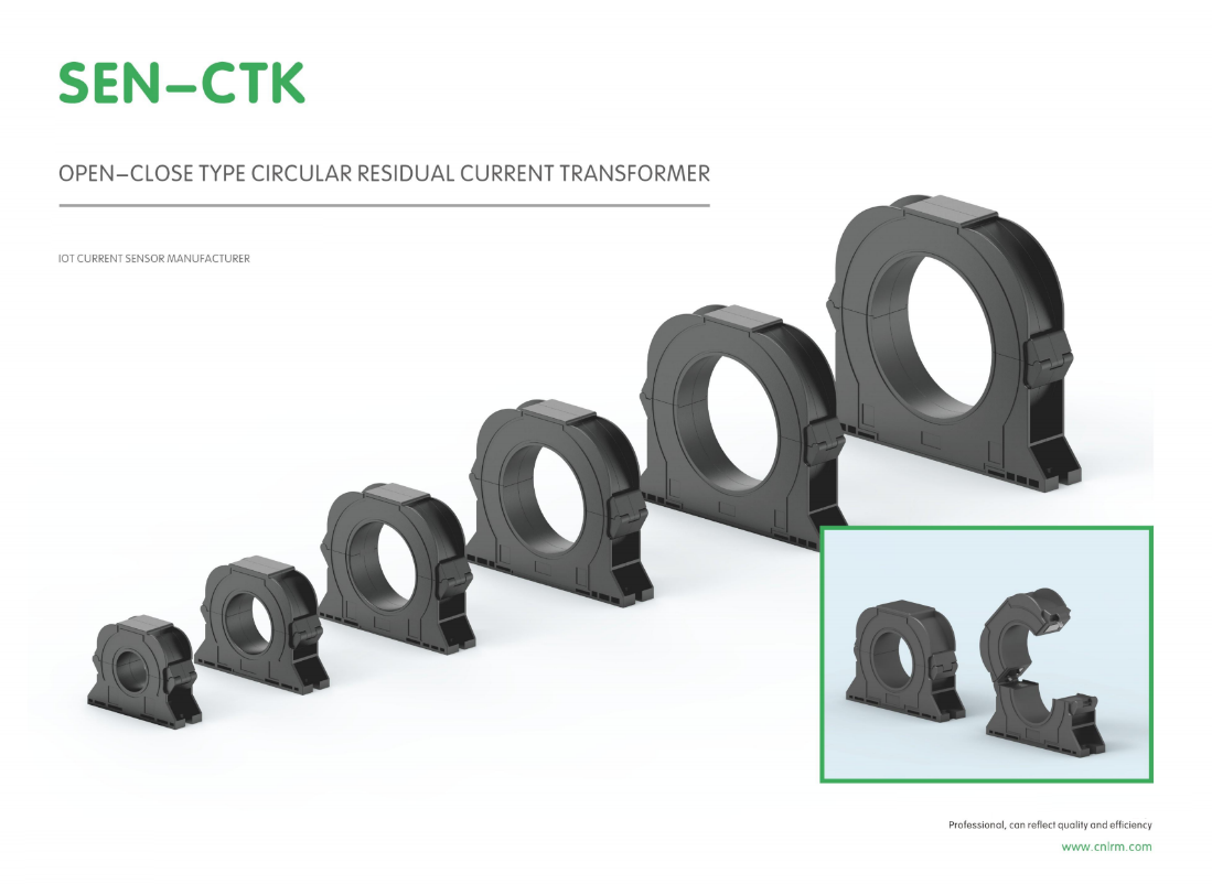
When sizing an aperture for conductor bundles, start by measuring the outer diameter of the dressed harness rather than summing individual conductor cross-sections. Parallel single-conductor cables never pack into a perfect circle; random bundle fill factors of 0.6 to 0.75 are typical, while controlled parallel rows require separate width and height calculations. Leave enough clearance so the outer jacket does not chafe against the edge of the penetration, and include room for stress cones, lugs, and heat-shrink transitions if these must pass through the opening.
Busbars add a second constraint because rectangular profiles and bolted joints need more space than an equivalent circular cable. In tight cabinets, an aperture sized only for the busbar cross-section often blocks access for torque wrenches or forces installers to bend the bar at an unsafe angle. Magnetic steel plates around busbar penetrations can also create local heating from induced eddy currents, so slotted openings or non-magnetic gland plates are worth considering when the gap between phases is already minimal.
A practical check after cutting the hole is to run the largest assembly through with the actual fasteners and insulation in place, then inspect under full load with a thermal camera. Edge distance from the aperture to cabinet walls should remain at least equal to the largest conductor diameter unless the enclosure is specifically reinforced, because a tight edge can propagate cracks from vibration or short-circuit forces. Adding ten to fifteen percent margin over the measured bundle diameter usually costs little and avoids expensive rework during commissioning.
Decoding Accuracy Class, Burden, and Output Signal Before You Quote
Accuracy class is not a universal green light. It describes the maximum percentage error a current transformer will introduce at a stated burden and usually at rated current, but the real behavior shifts as soon as the secondary wiring, relay, or meter draws a different load. A transformer stamped 0.5 can still push past that error band if the connected burden is heavier than the nameplate condition. Before a quote is finalized, it pays to check the operating range rather than relying on the class alone.
Burden is the impedance the secondary circuit presents, and it quietly decides whether the transformer can stay within its promised accuracy. If the actual burden exceeds the rated value, the core may start to saturate, distorting the output waveform and feeding the downstream device a signal that no longer represents the primary current faithfully. The output signal itself must also match what the relay or meter expects, whether it is a 1 A or 5 A loop or a low-energy voltage output. Decoding these three parameters together prevents the classic mistake of quoting a unit that works on paper but fails in the panel.
Why the Hinge and Latch Design Matters More Than You Think
Most people only notice a hinge or latch when it fails. A sticky hinge or a latch that needs a firm shoulder to close quietly changes how a door, gate, or cabinet feels every single day. The best designs disappear into the motion—opening with an almost weightless swing, closing with a soft, confident click. That kind of reliability isn't accidental; it comes from tolerances measured in fractions of a millimeter and materials chosen for thousands of cycles, not just the first impression.
There is also a hidden safety layer. A latch that engages fully keeps children away from medicine cabinets, holds toolboxes shut in a moving truck, and prevents a gate from swinging into traffic. Hinges that resist sagging under heavy lids protect fingers and keep edges aligned. When these small parts are under-specified, the result is not just annoying—it can be quietly dangerous.
Finally, the hinge and latch carry the character of the object. A tight, machined pin and a solid catch suggest care in places most people never look. It is a signal of how the maker thinks about the whole product: if they sweated the details that are felt but rarely seen, the rest of the design is likely just as considered.
Custom OEM Requests: Lead Time, Minimums, and Testing Proof
When you send over a custom OEM request, the first thing we look at is how much of the product you actually need. Small batch runs for prototypes or market tests can often be accommodated, but the minimums shift depending on whether we're dealing with standard blanks and a simple logo print or a fully re-engineered component. Lead times follow a similar logic: off-the-shelf components with light customization usually move through production faster than something that requires new molds or specialized finishing.
You won't be flying blind on compliance either. For any custom run, we provide the relevant testing proof—lab reports, material certifications, or stress test results—before your order ships. If your target market has specific standards, tell us up front and we'll pull together the documentation that matches. This keeps surprises to a minimum and gives you a clear paper trail for your own quality checks.
One thing that sets us apart: we'll give you a rough production timeline and minimum order quote within a couple of working days, not weeks. And if your quantities are below our standard threshold, ask anyway. Sometimes we can combine runs or suggest a near-equivalent stock option that gets you to market without waiting on a full custom setup.
Spotting Overpriced Claims and Under-Specced Units in Supplier Catalogs
A catalog page can make a mid-range motor sound like a precision instrument, but once you start comparing actual torque curves and duty cycles, the story shifts. Many suppliers lean on vague phrases like "high efficiency" or "industrial grade" without backing them up with measurable values. Pull the spec sheet for three supposedly similar units and you'll often find one delivers 15% less continuous torque at the same temperature rise, while another lists peak numbers that drop off sharply after two minutes. That's not a minor variation—it's the difference between a drive that runs 24/7 and one that trips thermal protection on a hot afternoon.
Another tell is the absence of curve data under realistic loads. A motor rated for 5 Nm at 3000 rpm looks impressive until you realize the catalog omits anything below 500 rpm, where many applications actually spend most of their time. Premium suppliers publish full speed-torque envelopes, including intermittent zones and voltage tolerance bands. If a catalog only shows a single operating point or hides derating factors in footnotes, treat that as a red flag. The same logic applies to gearboxes: a rated output torque of 200 Nm might only apply for 8 hours a day at 50% duty, while a unit rated for 160 Nm continuous could outlast it threefold.
Don't overlook the component-level details either. Bearing numbers, seal materials, and winding insulation classes tell you more about longevity than any marketing copy. A cheap unit might use open bearings with a low-temperature grease, while a properly specified alternative includes sealed bearings rated for 20,000 hours. Ask for the parts list or a teardown photo—suppliers who refuse usually have something to hide. Finally, compare warranty terms: a two-year warranty that excludes bearings and seals is not the same as a three-year full-coverage warranty. When the printed specs don't match the fine print, the real cost shows up in downtime, not on the invoice.
FAQ
It's a current transformer with a hinged core that can be opened and clamped around an existing conductor, used to measure the vector sum of currents in live and neutral conductors. When that sum isn't zero, it means leakage current is present. OEM versions are built to a manufacturer's specs so they can be integrated directly into a larger product line, like EV chargers, industrial control panels, or power distribution units.
The main reason is installation convenience. You don't have to disconnect cables or shut down an entire system to fit the sensor. The core opens, clips around the conductor, and locks back into place. This saves time during retrofits and reduces downtime, which matters a lot in facilities that run 24/7.
You'll find them in ground-fault monitoring for motor control centers, leakage current detection in data centers, EV charging infrastructure, solar inverters, and anywhere residual current protection is needed without interrupting the main circuit. They're also popular in retrofit projects where adding older-style toroids would be too disruptive.
Start with the rated residual current range, accuracy class, and burden. Then check the maximum conductor size the window can accommodate, the output type—millivolt, milliamp, or Modbus—and whether the split-core joint maintains performance after repeated opening and closing cycles. Also confirm the insulation level and operating temperature range match your environment.
Even tiny air gaps or misalignment at the mating surfaces can change the magnetic path and cause measurement drift. Quality OEM units use precision-machined core faces, strong clasps or screws, and sometimes a shield to keep dust and moisture out. It's worth asking for cycle test data to see how accuracy holds up after hundreds of open/close operations.
Yes, but you need to pick a model with a wide frequency response and low phase shift. Harmonics can cause false residual current readings if the core material saturates or if the electronics aren't designed for non-sinusoidal waveforms. Look for specifications that mention behavior under distorted waveforms, not just 50/60 Hz test results.
Many integrators prefer a millivolt output because it can feed directly into a microcontroller's ADC with a simple burden resistor. Others want a 4-20 mA loop or a digital Modbus output for longer cable runs and noise immunity. The choice depends on whether the transformer will be connected to a dedicated relay, a PLC, or a custom circuit board.
A big one is underestimating the conductor bundle size—cables with insulation and spacing take more window area than you'd think. Another is ignoring the temperature coefficient of the core material, which can shift the output in hot enclosures. Also, don't assume all split-core units perform equally after installation; request measured performance on a test rig with the actual cable arrangement.
Conclusion
In practice, the split-core residual current transformer earns its keep on retrofit jobs where downtime is expensive and existing conductors can't be disturbed. You're often working inside a cramped panel, so the aperture has to match not just the cable diameter but the whole bundle or busbar shape, including any insulation and tie wraps. A hinge that feels flimsy or a latch that needs a screwdriver to close is a warning sign—vibration and thermal cycling will eventually open a weak joint, causing false trips or missed leakage currents. Look for a core that closes squarely with a positive snap and no visible air gap at the mating faces.
Before you quote an OEM order, pin down the accuracy class, burden, and output signal you actually need. A 0.5-class unit with a 1 A or 5 A secondary may be overkill for a monitoring relay that only wants a voltage signal, while an undersized burden can push a good core into saturation. On custom requests, expect honest lead times of four to eight weeks, minimum order quantities that reflect tooling and test labor, and a test report showing ratio error and phase displacement for each production lot. When comparing catalogs, ignore inflated claims about "high precision" without stated class and be suspicious of units priced well below the cost of a proper mu-metal core. Ask for a sample with a calibration certificate before committing to volume.
Contact Us
Contact Person: Liu Mengyang
Email: [email protected]
Tel/WhatsApp: 8618727589233
Website: https://www.cnlrm.com/en/